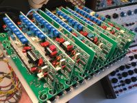
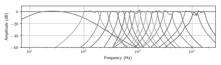
Two filter bank models, with modulation over all frequency band responses.
Perfect as a vocoder, a colorful graphic EQ, a VCF for synth voices, and a transient generator for percussion.
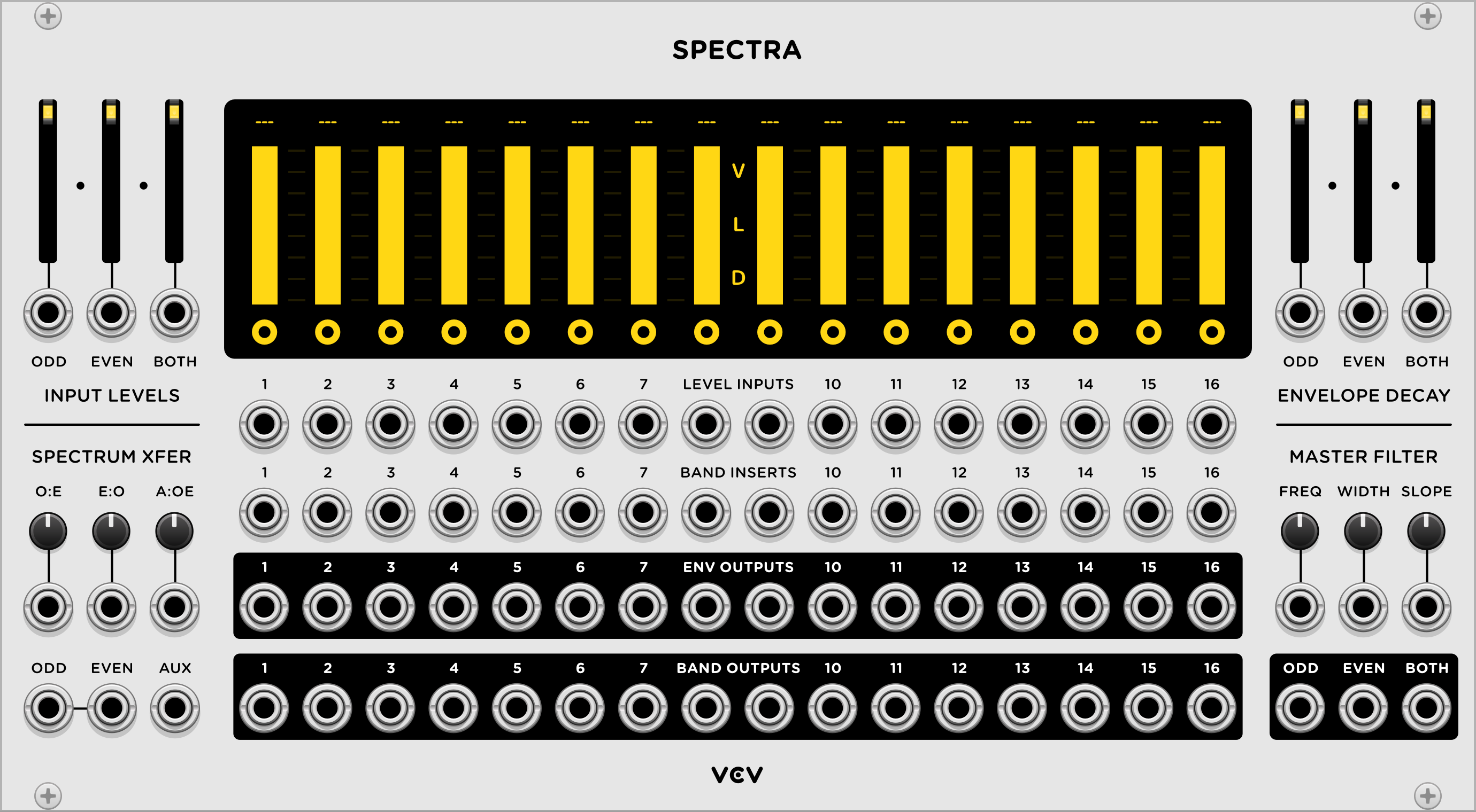
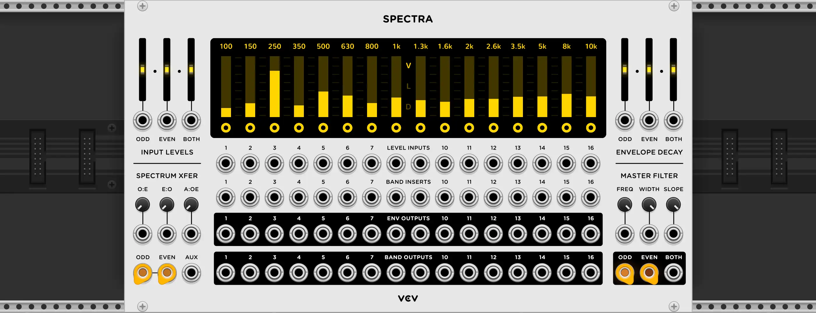
VCV Spectra
Spectra combines many filter bank and spectral processor concepts into a single module, but it follows one simple principle. Signals are split into multiple frequency bands, an amplitude adjustment is made to each band, and the bands are recombined into a single signal.
Signal Inputs/Outputs
The ODD and EVEN inputs on the bottom left of the panel route a signal into the odd-numbered (1, 3, 5, …) and even-numbered (2, 4, 6, …) bands. The inputs are normalized to each other, so if only one cable is patched into ODD or EVEN, that signal is routed to all bands. The AUX input isn’t routed to any bands, but the envelopes it generates are used in the Spectrum XFER section explained later.
The ODD and EVEN outputs on the bottom right of the panel are the mixed signals from all odd and even band outputs. The BOTH output is the sum of both odd and even (all) bands.
Input Levels
The ODD and EVEN faders and CV inputs apply up to 12 dB of pre-gain to the odd and even bands. The BOTH fader applies pre-gain to all bands. These levels also apply to signals patched into BAND INSERTS, described later.
Band Display
All 16 frequency bands are shown on the display. Click the V/L/D icons in the center of the display (or use the context menu) to change the display mode.
In Visual mode (“V”) the levels of each band are shown in real-time.
In Level mode (“L”) the level of each band can be adjusted.
In Decay mode (“D”) the envelope decay time of each band can be adjusted.
Band Inputs/Outputs
Each band has independent CV control of its own amplitude with the LEVEL INPUTS section. A CV signal, positive or negative, moves the virtual position of the display’s “Amplitude” handles.
To insert a signal directly into a filter band, patch a cable into one of the BAND INSERTS. Note that inserts interrupt the signal from the main ODD/EVEN inputs, so you can replace certain bands with different signals.
The ENV OUTPUTS section provides an envelope follower for each band, with its decay controlled by the display’s “Decay” mode or the Envelope Decay section.
The BAND OUTPUTS section generates audio processed by the band’s filter.
Spectrum XFER
The spectrum transfer feature allows you to cross-modulate one set of signals with another set of signals using the internal envelope followers of each band. This allows an ODD, EVEN, or AUX signal to control the frequency content of another signal. Each spectrum transfer knob and corresponding CV inputs crossfades between no transfer (hard-left) and full transfer (hard-right) for their particular transfer type.
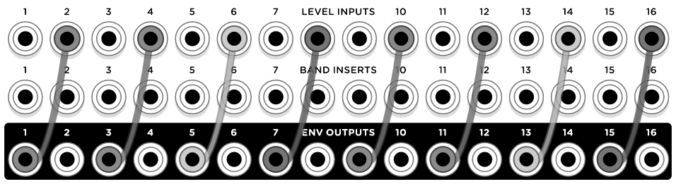
The E:O (even-to-odd) function applies the envelope of each even band to the next odd band’s amplitude. For example, if a transient appears in band #4, the amplitude of band #5 will reflect this transient. Similarly, the O:E (odd-to-even) function applies the envelope of each odd band to the next even band’s amplitude. This is similar to patching the ENV output of each even band to the next band’s VCA input, as illustrated below.
These functions can be used to construct a simple vocoder with the modulator signal applying the envelope of its 8 bands to the 8 bands of the carrier signal. For example, a human voice (modulator) patched into the ODD input can modulate a synth voice (carrier) patched into the EVEN voice using the O:E spectrum transfer.
A disadvantage of the E:O and O:E spectrum transfers is that only half the available bands are used for each signal. Although this method has its own sound/character and is used in a few classic hardware synthesizer modules, it is often desired to use all bands in the audible frequency range for the both the carrier and modulator signals. Achieving this in hardware requires owning two identical filter bank modules, but Spectra includes an AUX input which solves this problem with no duplication or extra patching.
A signal patched into AUX is processed internally to generate 16 envelope signals for each band, which is applied to all odd- and even-numbered bands. Note: Because generating AUX envelopes requires independently emulating a second set of 16 filter banks, the CPU power load of the module is increased by about 50% when the AUX input is patched.
Master Filter
In this section you can control the amplitude of all 16 bands with just three parameters, in a traditional lowpass/highpass/bandpass fashion.
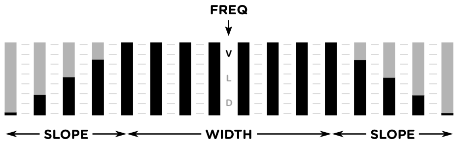
FREQ controls the center frequency of the bandpass filter. WIDTH specifies the width of the “plateau”. SLOPE controls the slope of each side of the plateau. With all three knobs hard-right, there is no attenuation of any bands. You must first decrease the width and slope to see/hear an effect.
Models
Spectra includes multiple filter bank models based on real hardware, as well as an “ideal” digital model, for adding your favorite character to your patches. Select a filter bank model by right-clicking on the panel and choosing a model.
- Vintage: Modeled on the 296r Spectral Processor, measured at 192 kHz.
- Digital: Generated using ideal brick-wall filters with precise frequency spacing, flat plateaus, and sharp slopes.