Module Manuals
- VCV VCO
- VCV Wavetable VCO
- VCV VCF
- VCV VCA
- VCV LFO
- VCV Wavetable LFO
- VCV Delay
- VCV ADSR EG
- VCV Mix
- VCV VCA Mix
- VCV 8vert
- VCV Mutes
- VCV Pulses
- VCV Scope
- VCV SEQ 3
- VCV Sequential Switch 1 to 4
- VCV Sequential Switch 4 to 1
- VCV Octave
- VCV Quantizer
- VCV Split
- VCV Merge
- VCV Sum
- VCV Viz
- VCV Mid/Side
- VCV Noise
- VCV Random
- VCV CV Mix
- VCV Fade
- VCV Logic
- VCV Compare
- VCV Gates
- VCV Process
- VCV Mult
- VCV Rescale
- VCV Random Values
- VCV Push
- VCV Sample & Hold Analog Shift Register
VCV VCO
A voltage-controlled oscillator generates raw tones at a particular frequency (pitch) and is the source sound generator of many types of synthesizer voices.
VCV VCO generates four shapes of waveforms: SIN (sine), TRI (triangle), SAW (sawtooth), and SQR (square). Each waveform contains different harmonics and therefore has a unique sound.

The width of the square waveform’s high portion is its pulse width, and it can be controlled by the PULSE WIDTH knob and modulated by the PWM (pulse width modulation) CV input and attenuverter. By default, the pulse width is 50% of the total waveform. Higher and lower pulse widths give reduced harmonics for a thinner sound.
The FREQ knob controls the pitch of the oscillator, with a range of 9 octaves. At its default value (12-o’clock position), the note C4 (middle C) is generated.
To control the pitch with another module, patch a CV signal into the V/OCT input or the FM input. The V/OCT input multiplies the frequency value using the 1V/octave standard, meaning that each volt of CV increases the pitch by 1 octave, doubling the frequency. Since there are 12 semitones in an octave, each 1/12 V increment increases the pitch by 1 semitone.
The FM input applies an additional pitch adjustment with an included attenuverter knob. With the FM attenuverter at 100%, the FM input functions similarly to the V/OCT input. At lower knob positions, a smaller adjustment is applied to the pitch, for subtle vibrato, for example.
The SYNC input resets the phase of each waveform when the sync signals passes upward through 0V. This behavior is more precisely called hard sync. If an audio-rate sync signal is used, the result is a waveform having characteristics of both the internal and sync frequencies.

Press the SOFT button to change the sync mode to soft sync. In this mode, instead of immediately resetting the phase of the waveform, the waveform direction is reversed each time a sync trigger is received. This produces a less harsh sound with lesser harmonics than a hard-synced waveform.

Press the LFM button to enable linear frequency modulation mode. In this mode, the oscillator’s frequency is adjusted proportionally to the FM voltage rather than exponentially. If modulated with a symmetric audio-rate signal, the oscillator holds its tuning, and the sound is similar to famous hardware examples such as the DX7.
Notes
If you view VCV VCO’s saw and square outputs on an oscilloscope like VCV Scope, you might notice a “ripple” or “wiggle” around the waveform’s jump discontinuities. This effect is called the Gibbs phenomenon and is the result of using an anti-aliasing algorithm to generate only frequencies below the Nyquist frequency (half the sample rate). Without anti-aliasing, digital oscillators can include harmonics that are not integer factors of the fundamental waveform. This creates a harsh, and some might say “cheap” or “cold”, sound.
VCV Wavetable VCO
A wavetable oscillator creates periodic waveforms by playing a short audio sample every cycle. Typically several of these waveforms are loaded into memory, allowing you to interpolate between them to vary the sound. The result is a rich and lively sound source that can be used for pads, leads, bass, drones, and more.
VCV Wavetable VCO is similar to VCV VCO but with additional features for wavetable synthesis.
By default, a simple wavetable called Basic.wav is loaded, containing four waves: sine, triangle, sawtooth, and square.

The WT POS knob changes the wavetable position, which selects the index of the wave sample in the wavetable. If the wavetable contains 4 waves for example, position 0% selects the first wave, 33.3% selects the second, 66.6% selects the third, and 100% selects the fourth. Intermediate values linearly crossfade between the two adjacent waves, so you can smoothly travel through the wavetable.

See the VCV VCO manual for details of all features shared between the two oscillators.
Loading external wavetables
You can load your own wavetables in .WAV format from any waveform editor such as WaveEdit. Right-click VCV Wavetable VCO’s panel and select “Load wavetable”. After selecting a file, select the wavetable’s number of “Wave points” in the context menu. If the waveform in the display shows 2 or more cycles, decrease the number of wave points. If half of a cycle or less is shown, increase the number of wave points.
Wavetables can contain up to 2^19 = 524,288 total samples.
.WAV files can contain 8, 16, 24, 32-bit integer, or 32-bit float samples.
Raw sample data can be loaded from the files extensions .s8, .s16, .s24, .s32, or .f32.
If the sample rate of a .WAV file is a power of 2 (such as 1024), the number of wave points is automatically set to this number.
WAV files having other sample rates (such as 48,000 Hz) must be set manually.
VCV VCF
A voltage controlled filter removes a range of frequencies from an audio signal, with its cutoff frequency controlled by an external voltage. Filters are used in many types of synthesizer patches to control the intensity or harmonic richness of audio signals.
VCV VCF models an analog 4-pole transistor ladder, a popular type of filter circuit designed in the 1960s. Audio from the IN input is processed through a low-pass filter (LPF) and high-pass filter (HPF).
The CUTOFF knob sets the characteristic frequency of the filter, the point where it begins to attenuate frequencies. If the cutoff attenuverter is set to 100%, the cutoff modulation input controls the frequency with the 1V/octave standard.
The RES knob controls the filter resonance, which emphasizes the signal near the cutoff frequency. At high resonance values, VCV VCF self-oscillates, creating feedback from its own internal noise near the cutoff frequency.

The DRIVE knob adds gain to the input signal which is saturated by the filter circuit model. This creates a dirtier, grungier filter sound.

VCV VCA
A voltage controlled amplifier applies gain/attenuation to an audio or CV signal according to another CV signal. For example, you can control the volume level of a synth voice with an envelope generator or sequencer.
With VCV VCA, a signal passing through IN to OUT is attenuated based on the CV input signal from 0% at 0V, to 100% at 10V. CV input is clamped, meaning that negative CV or CV beyond 10V results in 0% and 100% attenuation, respectively.
The amount of gain is displayed by the vertical yellow bar in the display. You can apply manual level attenuation by clicking and dragging the display up or down.
Settings
By default, VCV VCA applies mathematically-ideal linear amplification, so the output signal follows the equation OUT = IN × (CV / 10V).
For example, a CV signal of 5V attenuates the input signal by 50%.
However, many hardware modular VCA’s apply exponential amplification, so you can enable this behavior by right-clicking the panel and enabling “Exponential response”. In this mode, the upper range of CV applies more accelerated level changes than the lower range, giving envelopes a more aggressive response.

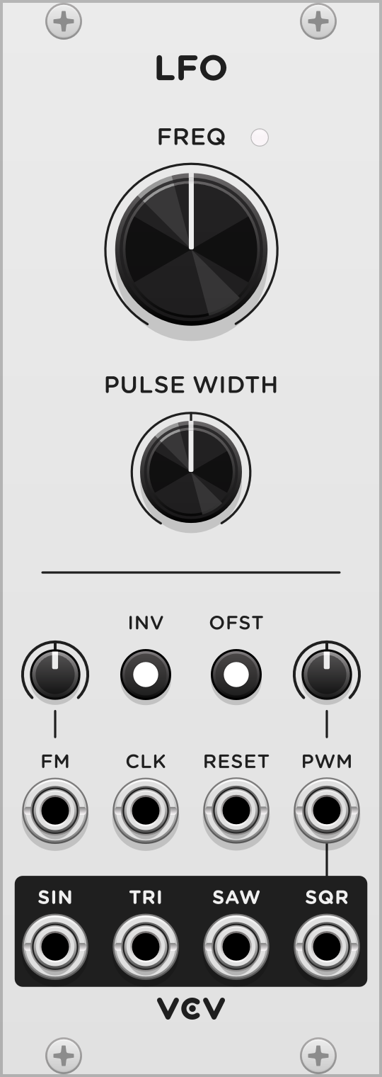
VCV LFO
A low frequency oscillator is a voltage-controlled oscillator that is designed to oscillate at lower frequencies than audio rates. VCV LFO is nearly identical to VCV VCO, with a few differences.
The range of the FREQ knob is much lower than VCO, ranging from one oscillation roughly every 4 minutes to about 1000 Hz.
The OFST (offset) switch toggles between unipolar (0V to 10V) and bipolar (-5V to 5V) output. In both of these modes, the peak-to-peak voltage difference is always 10V.
The INV switch inverts (flips) the output signal. In unipolar mode, this inverted signal still oscillates between 0V and 10V.
The CLK input synchronizes the frequency (but not the phase) of LFO to a clock trigger. When a clock is patched, the FREQ knob multiplies the frequency, with a 1x factor at its default (12 o’clock) position.
The RESET trigger input behaves similarly to the SYNC input of VCO.

The output signals generated by LFO are similar to VCO but without anti-aliasing, so there is no Gibbs effect. This makes LFO more suitable for generating CV for modulation, while VCO is more suitable for generating audible waveforms.
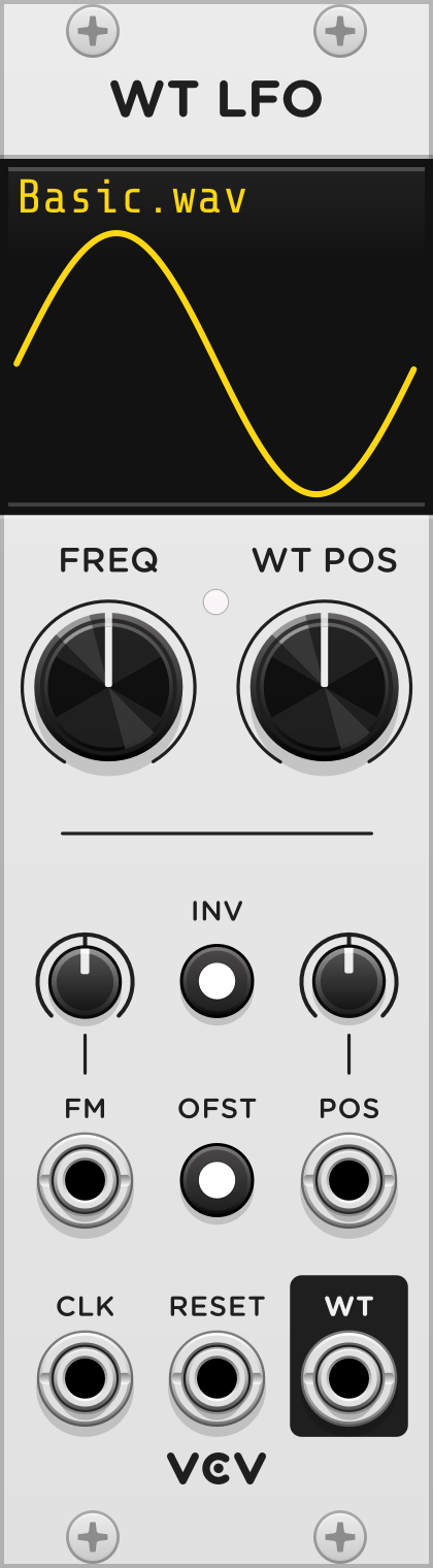
VCV Wavetable LFO
VCV Wavetable LFO is a low-frequency oscillator similar to VCV Wavetable VCO, including the same differences between VCV LFO and VCV VCO.
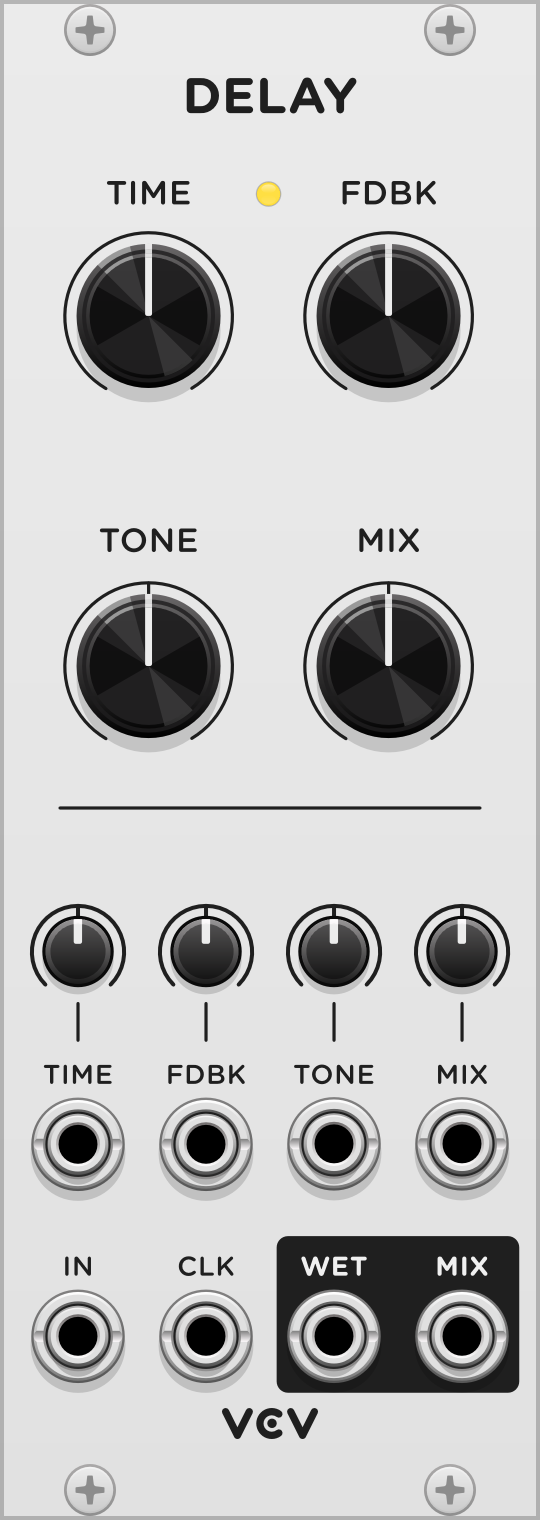
VCV Delay
A delay effect records an audio signal and plays it back after some amount of time. Early delay hardware used analog tape loops to write and record with different magnetic heads, while most modern delay effects record digital signals using a memory buffer. In either case, repeated “taps” of delay can be added using a feedback loop with optional EQ.

The delay TIME of VCV Delay can be adjusted from 1 ms to 10 seconds. When the TIME CV attenuator is set to 100%, the CV input controls the time using the 1V/octave standard, meaning that each additional volt of CV decreases the time by half (i.e. increases the frequency by 2).
The WET output plays the wet (delayed) signal. The MIX knob adjusts the balance between the dry (input) and wet (delayed) signal in the MIX output.
The TONE knob controls a DJ-style filter, low-pass filtering the wet signal when turned to the left and high-pass filtering when turned to the right.
The FDBK knob adjusts the level of feedback of the post-filtered wet output into the delay processor.
The delay time can be synchronized to a clock when it is patched to CLK. When patched, the TIME value multiplies or divides the clock frequency.
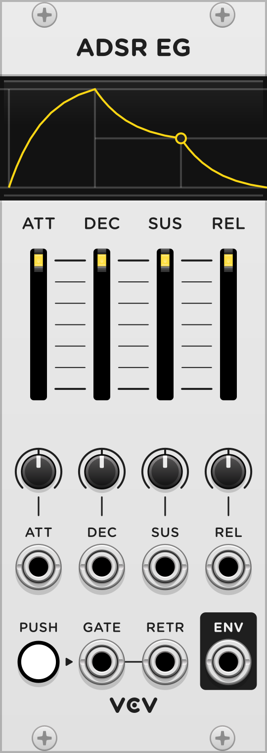
VCV ADSR EG
An envelope generator (EG) converts a gate, having only an on and off state, into a control voltage (CV) signal with a musically useful shape. They are often used to control VCAs, VCF cutoff frequencies, or any modulation inputs.
The ADSR envelope generator was developed in the 1960s as an attempt to emulate the behavior of physical instruments such as the piano. It has four parameters:
- Attack (ATT): Rising time while gate is HIGH.
- Decay (DEC): Falling time while gate is HIGH.
- Sustain (SUS): Target CV level while decaying.
- Release (REL): Falling time when gate is LOW.

VCV ADSR EG is activated by a GATE signal or by clicking and holding the PUSH button. An envelope CV signal is generated at the ENV output, ranging from 0V to 10V.
The current stage is shown by the 4 slider lights. Although ADSR envelope generators only have 3 actual stages (attack, decay, and release), VCV ADSR EG illuminates the sustain light when the envelope has reached the sustain target level during the decay stage.
An optional RETR (re-trigger) signal can be used to reset the envelope back to the attack stage. This is useful if you want to play legato notes with VCV MIDI to CV while resetting the envelope when each new key is pressed. If you play multiple legato notes, the gate signal remains HIGH between them, so a RETR trigger is needed to notify VCV ADSR EG that a new note is being played.


VCV Mix
VCV Mix is a simple 6-channel unity-mixer with output level adjustment. It can mix both audio and CV signals.
All patched signals are summed and then attenuated with the LEVEL knob. When LEVEL is at its default position (100%), VCV Mix becomes a unity mixer.

Settings
Right-click the panel and click “Invert output” to multiply the output voltage by -1, as if the LEVEL knob has a range of 0% to -100%. This can be useful for inverting the phase of audio, or reversing the direction of control voltage.
Enable “Average voltages” from the context menu to divide the output voltage by the number of currently patched inputs. This can be useful for scaling the output range to the same range as all patched CV signals. For example, if four 10V signals are patched with one 0V signal, the output voltage is 8V (with 100% LEVEL). With this mode disabled, the output is 40V in this example, which is often too large for modulating modules.
VCV VCA Mix
VCV VCA Mix is a simple 4-channel mixer with a voltage-controlled amplifier (VCA) on each channel, as well as the mixed output.
Each input IN 1–4 is amplified by the CV 1–4 signal (from 0–10V) if patched, and its level is adjusted with its corresponding fader. The signal (post-VCA and post-fader) is then sent to each CH 1–4 channel output.
After mixing all 4 channels, the mixed signal is amplified by the CV signal if patched, and its level is adjusted with the MIX knob. The signal is then sent to the MIX output.

Settings
Right-click the panel to enable “Exponential channel VCAs” or “Exponential mix VCA” to use exponential response instead of linear response for all channel CV inputs or the mix CV input. Exponential response behaves similarly to many hardware VCAs, while linear response is more mathematically straightforward.
VCV 8vert
VCV 8vert is utility module with 8 inputs, 8 attenuverters, and 8 outputs. An attenuverter is an attenuator that can apply both positive and negative gain.
Each attenuverter can apply a gain ranging from -1 to 1. In each knob’s initial position at 12-o’clock, a gain of 0 is applied, resulting in a silent output signal. Turned hard-right, the input signal passes through to the output without modification, and turned hard-left the input is inverted, flipping its value.
The top input of VCV 8vert is normalized to 10V, meaning that a constant 10V signal is used instead when no cable is patched. All other inputs are normalized to the input above it, allowing inputs to “copy” their signal downward.
When no inputs are patched into a channel and all channels above it, these inputs are all effectively normalized to 10V. This turns 8vert into a constant voltage generator with voltages set by each of the attenuverters from -10V to 10V.
If a cable is patched into the first input only, all channels below it receive the same signal and can attenuvert it independently based on each attenuverter’s position.

VCV Mutes
The VCV Mutes utility module contains 10 rows of switches, allowing quick control over muting signals. Click a button to toggle the mute state of each channel.
Each input is normalized to the input directly above it. In other words, all inputs “copy” their signal to the channel below it. For example, Mutes is able to function as a multiple module that copies one input to up to 10 outputs, with additional mute control for each output.
Like other modules, you can randomize and initialize the module’s state with the context menu or key commands.
VCV Pulses
VCV Pulses contains 10 rows of manual trigger and gate generators.
Click a PUSH button to generate a 1 millisecond, 10V pulse signal (based on the VCV trigger standard) in the adjacent TRIG output.
While the PUSH button is held, the GATE output generates 10V, otherwise it generates 0V.
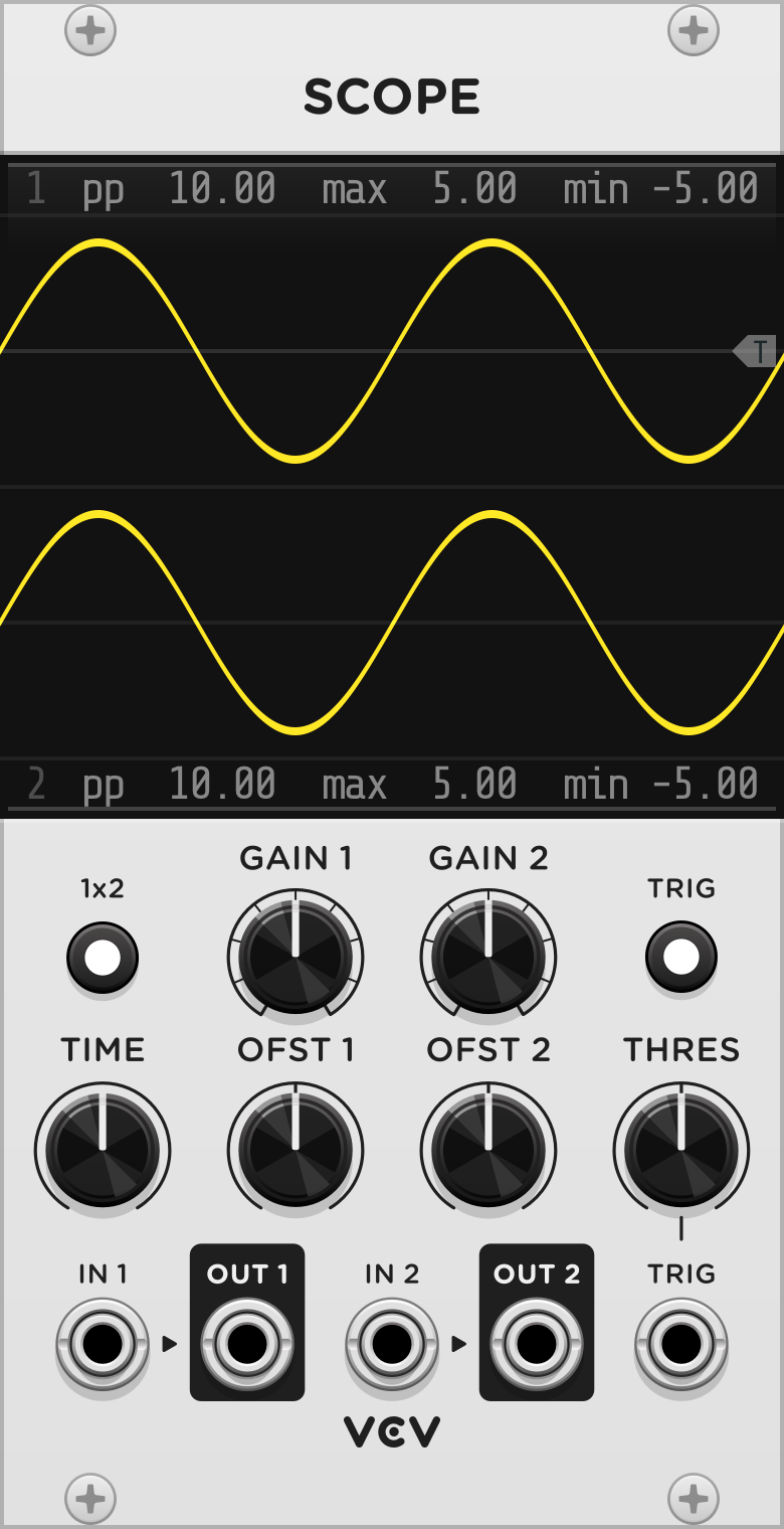
VCV Scope
An oscilloscope visualizes voltage signals over time. The design and functionality of VCV Scope is based on vintage analog oscilloscopes, which are popular tools among Eurorack synthesizer users for understanding CV and audio signals.
Patch any cable into IN 1 or IN 2 to see its voltage over time. Outputs OUT 1 and OUT 2 are provided for convenience to pass the signal through to other modules if needed.
The TIME knob zooms the screen horizontally, displaying a duration as short as 5 milliseconds to as long as 50 seconds.
The GAIN 1 & 2 knobs zoom the screen vertically, displaying a voltage range as much as 20 V peak-to-peak (pp) to as little as 0.078 V. The OFST 1 & 2 knobs pan the screen vertically, effectively applying a voltage offset to the signal before zooming.
Directly above and below the scope display are the the minimum, maximum, and peak-to-peak voltage (pp, equal to max - min) of both signals in the viewport.
Click the TRIG button to enable trigger mode, which is useful for synchronizing the display to the beginning of periodic audio-rate signals. In this mode, the scope does not start measuring either signal until the IN 1 voltage passes upward through the threshold voltage. This threshold is set from the THRES knob and shown on the display with a T symbol. Alternatively, an external trigger in the TRIG input can be used instead of IN 1 to start measuring.

2D mode
Click the 1x2 button to switch from 1&2 (dual) mode to 1x2 (2D) mode. In this mode, the IN 1 signal controls the horizontal (X) position of the scope, while IN 2 controls the vertical (Y) position.

The TIME knob controls the rate of sampling. If monitoring two audio-rate signals, set TIME to a fast sampling rate to display smooth, accurate curves. For slower CV-rate signals, adjust TIME to control the length (memory) of the scope path.
If two sine waves of different frequencies are monitored in this mode, a Lissajous curve appears. Experiment with different waveforms and frequencies to draw interesting shapes in 2D mode!
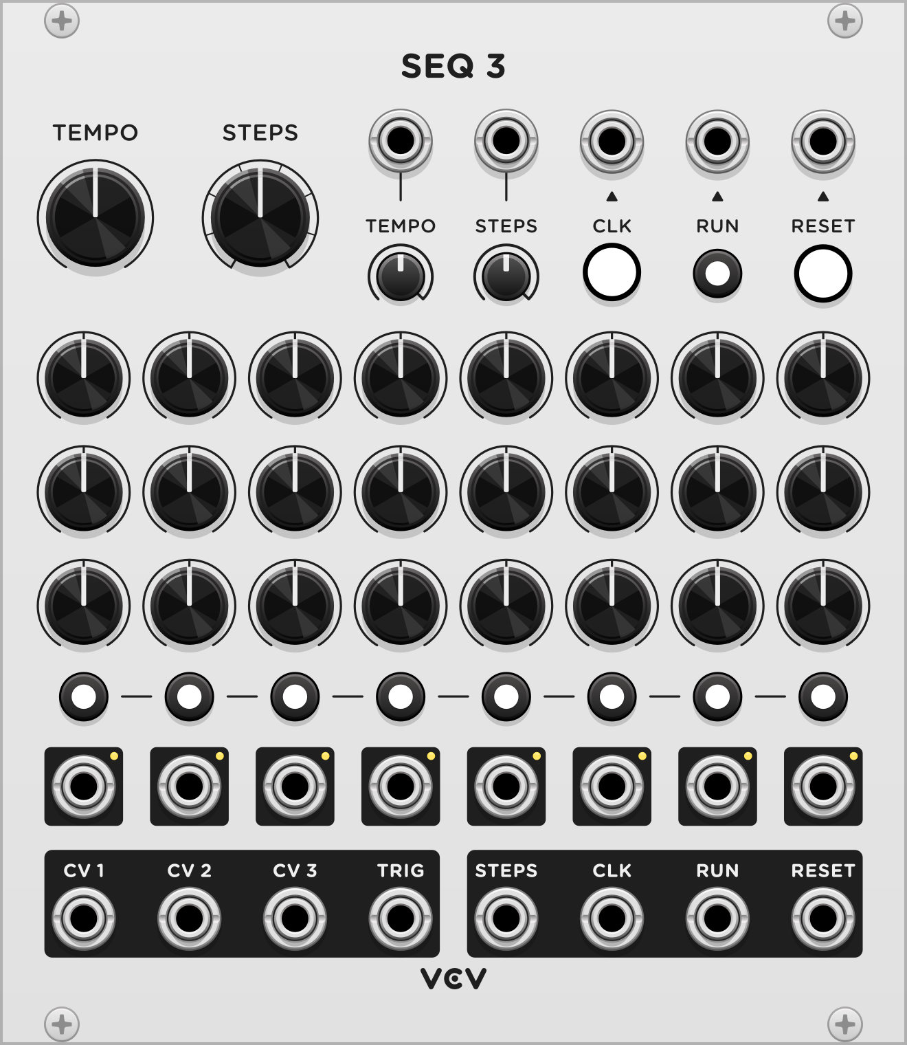
VCV SEQ 3
A sequencer can be used to program patterns of melodies, control voltage, or triggers for playback. VCV SEQ 3 can sequence up to 8 steps, each with 3 channels of CV and 1 channel of triggers.

The module’s step position is advanced by either an internal or external clock. The TEMPO knob sets the rate of the internal clock and can be modulated with the TEMPO input. When the TEMPO CV attenuator knob is set to 100%, the tempo is adjusted by exactly 1V/octave. If a cable is patched into CLK, the internal clock is ignored, and the sequencer advances only when a clock trigger is received.
The STEPS knob sets the number of steps in the pattern. After the last step in the pattern is reached, an additional clock resets the step position to 1, and the RESET output emits a trigger. The step position can also be reset with the RESET button and trigger input.
The CV values and trigger states can be set for each step using the array of knobs and buttons. The row of STEP outputs indicates the current step position via a light and 10V gate signal. The CV 1, CV 2, CV 3, and TRIG outputs emit the values at the current step.
The RUN button and trigger input toggles the playback state. When not running, both internal and external triggers are ignored, so the step position does not advance. When the run state is toggled, the RUN output emits a trigger.
Multiple instances of VCV SEQ 3 can be synchronized by patching the STEPS, CLK, RUN, and RESET outputs of one instance into the corresponding inputs of another instance. The STEPS knob of the second instance must be set to 1 in order to set the correct number of steps.
Settings
Normally the TRIG output emits a 1 millisecond pulse when advancing to a step with an enabled trigger. Some hardware sequencers instead pass the external clock gate (however long it may be) through to the TRIG output if the step’s trigger is enabled. This behavior can be enabled by right-clicking the panel and clicking “Clock passthrough”. When using the internal clock with this mode enabled, the TRIG output emits a gate with a 50% duty cycle.
If needed, the pattern’s rows can be shifted left or right by right-clicking the panel and clicking “Rotate left” or “Rotate right”. As with most menu items in VCV Rack, you can hold Ctrl (Cmd on Mac) when clicking to keep the context menu open to rotate multiple times.


VCV Sequential Switch 1 to 4
VCV Sequential Switch 4 to 1
A sequential switch routes a single input to one of multiple outputs, or routes one of multiple inputs to a single output. The choice of input/output can be switched with a trigger.
VCV Sequential Switch comes in two variants: 1 input to 4 outputs, and 4 inputs to 1 outputs. You can select 2, 3, or 4 inputs/outputs with the STEPS switch. If less than 4 steps, a red light is shown next to all inaccessible inputs/outputs.
Trigger TRIG to cycle through these steps. A yellow light is shown next to the active step. Trigger RESET to reset the step to 1.

Settings
If processing audio signals, a click may occur when advancing steps. It is recommended to enable de-clicking (common on analog mixers) by right-clicking the panel and selecting “De-click”.

VCV Octave
Octave shifts a 1V/oct pitch signal by whole octaves, ranging from -4 to +4. Patch a pitch signal into IN, and the shifted pitch signal is at OUT. If no cable is patched into IN, Octave generates fixed whole number voltages.
For pitch signals that follow the “1V/octave” standard, Octave adds/subtracts 1V to shift it up/down by one octave, as the standard’s name would suggest. This makes Octave a very simple module to understand and use.
To specify the number of octaves to shift, click on a circle in the main display. Circles above the middle circle represent upward octave shifts, and circles below it represent downward octave shifts. Octave’s display is a normal parameter, so you can right-click it to manually enter a shift amount, map the parameter with VCV MIDI-Map, etc.
The octave shift amount can be modulated with CV and is computed by taking the nearest whole number voltage of the CV input.
Starter tips
To create a sub oscillator, duplicate your main VCO and place an Octave module between the pitch source and the new VCO. Set the octave shift amount to -1, and mix the two VCO’s waveforms with VCV VCA Mix.

VCV Quantizer
Quantizer rounds a 1V/octave pitch signal to the nearest enabled note. By default all notes in the chromatic scale are enabled, so Quantizer simply rounds the pitch signal to the nearest 1/12 V.
Toggle notes by clicking or dragging on the piano-style display. Dozens of scales are included as factory presets, which can be accessed by right-clicking on the panel.
The OFFSET knob adds voltage/semitones to the pitch signal before being quantized.
To easily change the key of the quantizer’s scale, right-click the panel and select “Shift notes up/down”. Note that if you want to shift your melody’s root note, you must either pre-offset the pitch with OFFSET, or post-offset the 1V/oct signal using the frequency knob of your oscillator or sound generator.
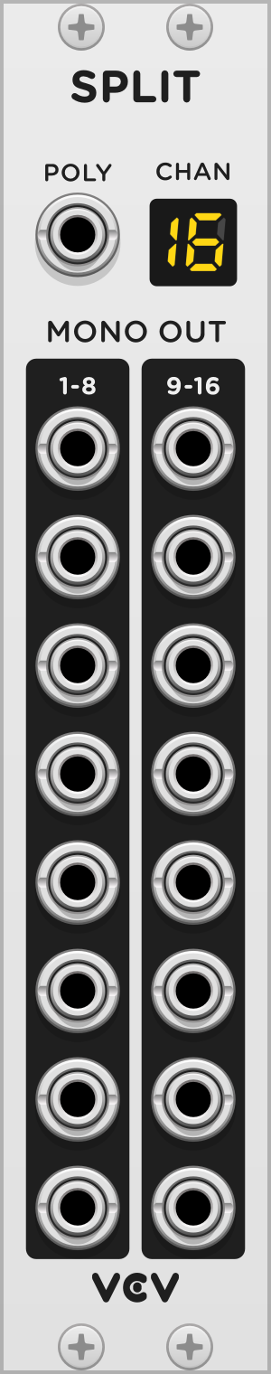
VCV Split
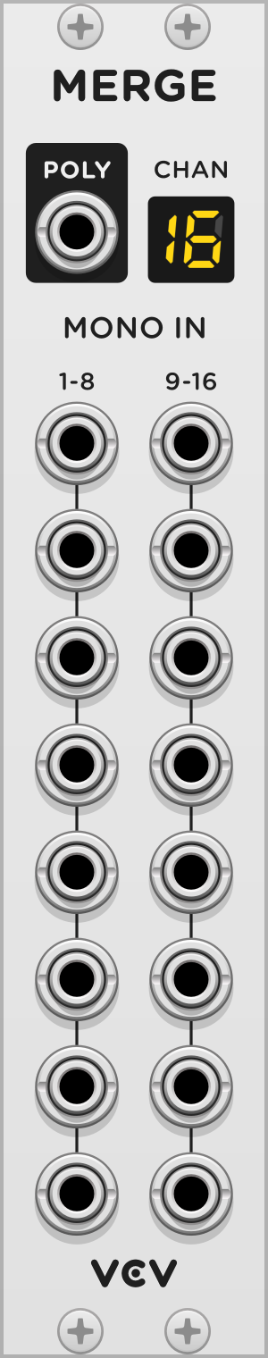
VCV Merge
Split and Merge convert polyphonic signals to multiple monophonic signals and vice-versa. Refer to the Polyphony entry of Rack’s manual to learn about polyphony in Rack.
Split expands a polyphonic signal patched into the POLY input to multiple monophonic outputs labeled 1-8 and 9-16. If the polyphonic input signal includes less than 16 channels, all unpatched channels are considered to be 0V.
Merge joins multiple monophonic channels into one polyphonic signal at the POLY output. By default, the number of polyphonic channels is the index of the highest patched monophonic input. For example, if you only patch a cable to input 4, the polyphonic output will have 4 channels. Unpatched inputs are considered to be 0V. You can explicitly specify the number of output channels by right-clicking on the panel and selecting the “Channels” menu.
It is possible to create zero-channel polyphonic signals with Merge. See Polyphony Technical Details for an explanation of zero-channel cables.
The CHAN lights on both Split and Merge modules indicate the number of channels currently being processed. It is not possible to “deactivate” channels lower than the maximum channel number. All channels from 1 to the maximum channel number are “active”, even if they are 0V.

VCV Sum
Sum mixes all channels of a polyphonic signal patched into the POLY input to produce a monophonic signal at the MONO output.
The CHAN lights indicate the number of channels Sum is mixing.
Summing multiple audio signals usually results in an increase of audio levels, so you can account for this by adjusting the OUT level. Pay attention to the LEVEL VU meter to avoid clipping. For example, a four-voice polyphonic signal can increase the peak amplitude by 4, so it is a good idea to apply roughly 25% attenuation with Sum.

VCV Viz
Viz visualizes the voltages of each channel of a polyphonic signal.
Patch a polyphonic signal into the POLY input. Active polyphonic channels are represented by white channel numbers. The light on the right of each channel number emits green for a positive signal, red for a negative signal, and yellow (rapidly blending red/green) for an audio-rate signal.
Starter tips
Patch VCV MIDI to CV’s GATE output to Viz, set the desired number of polyphonic channels by right-clicking on MIDI to CV’s panel, and play chords with your MIDI keyboard (or computer keyboard). This will make it easier to see how MIDI to CV maps notes to each channel of the polyphonic gate signal. Try a different “Polyphony mode” with MIDI to CV’s right-click menu and notice the different behaviors when playing chords.
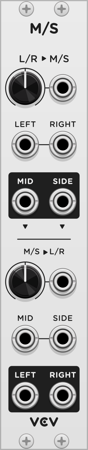
VCV Mid/Side
VCV Mid/Side converts L/R stereo signals to M/S stereo signals and vice-versa.
Typically, stereo signals contain a left and right channel, representing the signals played by the left and right speakers. An alternative method is to use a “mid” (middle) channel, representing the signal if it was converted to mono, and a “side” channel, representing the amount of left/right bias. In other words, the mid channel is the sum of the left and right channels, and the side channel is their difference.
The WIDTH knob and CV input increases or decreases the stereo width during encoding or decoding. This is done by simply applying a gain to the side channel.
The inputs of the decoder are normalized to the encoder’s outputs, so you can use Mid/Side as an L/R stereo widener. Patch a L/R signal into the encoder’s inputs, set WIDTH on either section, and use the L/R signal on the decoder’s output.
The formulas for each output are
M = (L + R) / 2
S = (L - R) / 2 * WIDTH
L = M + S * WIDTH
R = M - S * WIDTH
Starter tips
Mid/side stereo is useful for a number of reasons, such as processing the mid/side channels in separate ways to create symmetrical stereo effects. For example, you can use a mono reverb on the mid channel to apply a bit of reverb to the center of a stereo signal while still roughly preserving stereo image. It’s not perfect, but it’s better than mono—try it!
Expert tips
A mid/side stereo microphone setup can produce mid/side signals directly by using a cardioid or omnidirectional microphone for the mid channel and a figure-8 microphone for the side channel. After calibrating the microphone levels or by adjusting the WIDTH knob to taste, VCV Mid/Side can decode these channels into left/right stereo. To reverse the stereo image, you can either invert the polarity of the side channel or just swap the left/right channels.

VCV Noise
VCV Noise generates 7 colors of noise, each with a different characteristic and frequency response.

White noise (WHT output) has equal intensities at all frequencies. Each voltage is sampled from a normal distribution.
Pink noise (PINK output) has more bass than white noise, and its intensity decreases by -3 dB/octave.
Red noise (RED output) has more bass than pink noise, and its intensity decreases by -6 dB/octave.
Violet noise (VIOL output) has more treble than blue noise, and its intensity increases by +6 dB/octave.
Blue noise (BLUE output) has more treble than white noise, and its intensity increases by +3 dB/octave.
Gray noise (GRAY output) is calibrated to a psychoacoustic equal loudness curve. The human ear does not hear all frequencies with equal intensity (e.g. white noise sounds louder around 1000 Hz than 100 Hz, although its actual power density is the same), so a filter with an equal loudness frequency response is needed to produce noise that sounds uniform across the audible frequency range. In particular, the gray noise generated by VCV Noise is inverse A-weighted.
Black noise (BLK output) has no single standard definition, so VCV Noise defines it as “uniform noise”, i.e. voltages sampled from a uniform distribution. Uniform noise has nearly the same frequency response as white noise, except that it contains aliasing. This effect is similar to early digital noise generators or poorly-designed software noise algorithms. However, uniform noise is useful for sample-and-hold sources, CV, and other non-audio purposes.
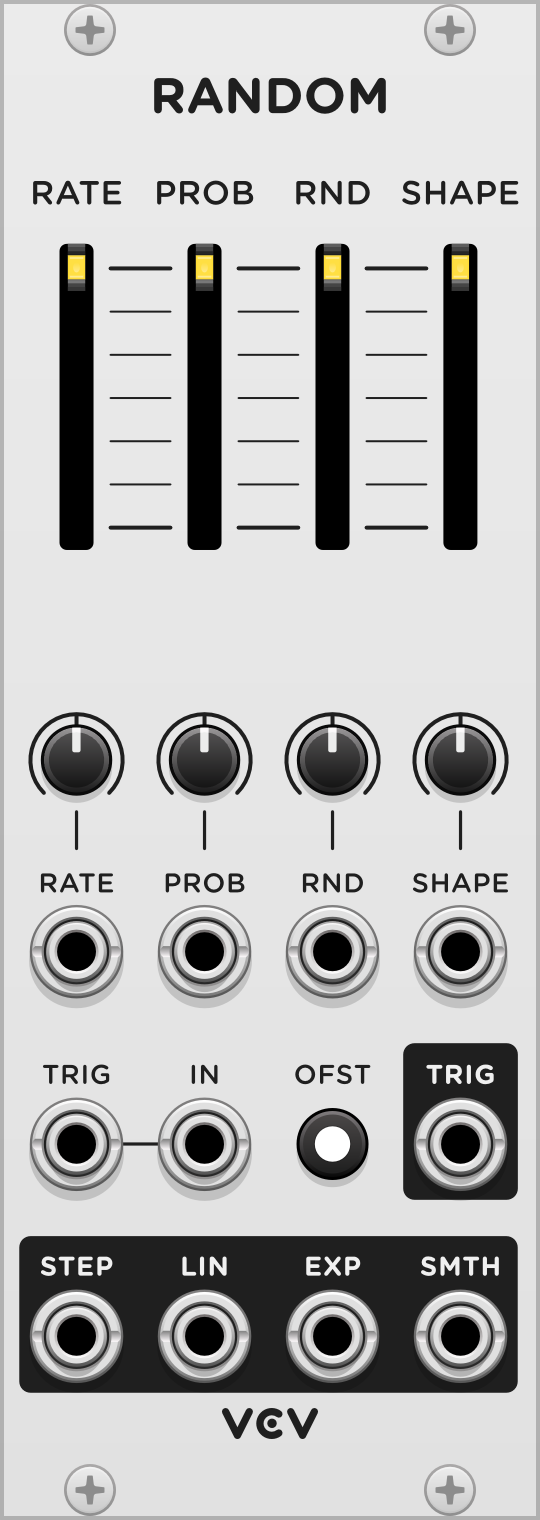
VCV Random
VCV Random is a random CV generator with 4 types of randomness and a triggerable sample-and-hold function.

The RATE slider sets the tempo of the internal clock. The CV input below the slider adjusts the clock rate, with 1V/oct calibration when the CV attenuverter is 100%. Upon each clock trigger, the RATE slider light blinks, and there is a chance for the internal random source to generate a new value. This probability is set by the PROB slider, and if a new value was generated, the PROB slider light blinks and a pulse is emitted from the TRIG output.
When the internal random source generates a new value, it mixes the previous value with a random value, with an amount specified by the RND slider. If RND is 100%, the result is fully random and not dependent on the previous value. If RND is 0%, the result always equals the previous value. If RND is between these extremes, the result is random but near the previous value by some margin.

If the TRIG input is patched, the RATE slider is ignored, and the clock is only triggered when an external trigger is received. The PROB slider is used to filter this trigger by some probability.
If the IN input is patched, this external voltage is used instead of a random voltage upon each trigger. The RND slider has no effect.

The SHAPE slider sets the shape of all four random outputs. At its lowest position (0%), all outputs immediately jump to the new random value (the target value) when the clock is triggered. At non-zero positions, the outputs interpolate between the previous and the target value, using a different behavior for each output.

-
The STEP output interpolates by a number of equally-spaced steps. At 0% shape, the output jumps directly to the target value in 1 step. At 100% shape, there are 16 steps between the previous and the next clock trigger.
-
The LIN output interpolates linearly with a slope specified by the shape. At 0% shape, the line has infinite slope, jumping directly to the target value. At 100% shape, the output takes the entire clock cycle duration to reach the target value. At intermediate values, the output reaches the target value and holds until the clock cycle finishes.
-
The SMTH output interpolates smoothly between values using sine interpolation. The speed of the interpolation is specified by the shape, and the output holds at the target value until the clock cycle finishes.
-
The EXP output uses exponential interpolation, with its time constant specified by the shape. At 100% shape, the interpolation becomes linear.
The OFST (offset) switch toggles between unipolar (0V to 10V) and bipolar (-5V to 5V) output voltages.

VCV CV Mix
CV Mix combines up to 3 CV signals, or a fixed voltage offset, into a single CV signal that can control a single parameter of a module.
Each -/+ level knob attenuverts its corresponding CV input by -100% to 100%. The CV signals are then summed to the MIX output.
All inputs are normalized to 10V, so adjusting the level of an unpatched input adds a voltage of -10V to 10V to the output.

Starter tips
By leaving one input unpatched, you can attenuvert, sum, and offset 2 CV inputs. Adjust the unused -/+ knob to set the offset applied to the output.
Expert tips
The MIX voltage can be summarized by the formula
MIX = CV1 * LEVEL1 + CV2 * LEVEL2 + CV3 * LEVEL3
If unpatched, CV = 10V.

VCV Fade
This utility balances or crossfades two audio or CV signals between one or two outputs.
The FADE knob and CV input specifies the balance between the IN 1 and IN 2 signals. When FADE is hard-left, IN 1 is sent directly to OUT 1, and IN 2 is sent to OUT 2. When FADE is hard-right, the outputs are swapped.
At intermediate positions, the signal levels are linearly crossfaded between these extremes. For example at 50%, both outputs are the average voltage of IN 1 and IN 2.

Settings
Right-click the panel to set the “Pan law” setting to -6 dB (linear, recommended for CV) or -3 dB (recommended for audio). -3 dB pan law applies a nonlinear (square root) scaling to each input gain, boosting the center FADE position by +3 dB relative to linear scaling. This produces a more natural pan when the outputs are used as a stereo L/R signal.
Starter tips
If only one output is used, the FADE parameter crossfades between two inputs, selecting them directly at the extremes.
If only one input is used, the FADE parameter specifies the balance between two outputs. If used as a stereo L/R signal, FADE adjusts the stereo pan.
Expert tips
The output voltages can be summarized by the formulas
OUT1 = IN1 * (1 - FADE) + IN2 * FADE
OUT2 = IN1 * FADE + IN2 * (1 - FADE)
where FADE is limited between 0 and 1.
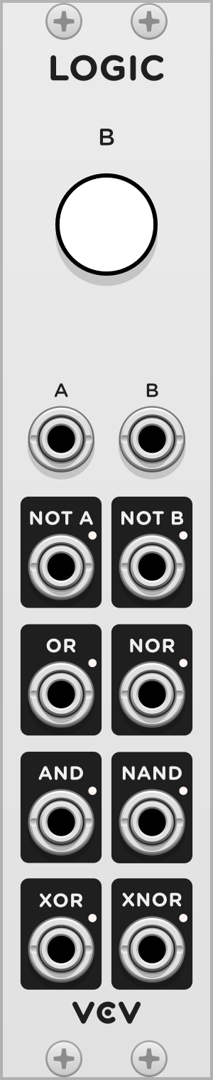
VCV Logic
This gate processor applies Boolean logic operations to gate signals A and B.
In VCV Rack, a gate signal can be HIGH (usually 10V), representing an ON/TRUE state, or LOW (usually 0V), representing an OFF/FALSE state.
When the B button is pressed, the B signal is set to a HIGH state regardless of the B gate voltage.
-
The NOT A and NOT B outputs negate/invert the state of A and B, respectively. For example, NOT A is HIGH when A is LOW, and it is LOW when A is HIGH.
-
OR is HIGH when either A or B is HIGH, or both.
-
NOR is HIGH when neither A or B is HIGH.
-
AND is HIGH when both A and B are HIGH.
-
NAND is HIGH when A and B are not both HIGH.
-
XOR is HIGH when either A or B is HIGH, but not both.
-
XNOR is HIGH when both A and B are HIGH, or when neither are HIGH. In other words, XNOR is HIGH when the state of A is equal to the state of B.
This information can be summarized in a truth table for all 4 possible input configurations of A and B. HIGH/true states are shown as a black circle ⬤, while LOW/false states are shown as a white circle ◯.

When two arbitrary gate signals A and B are combined with VCV Logic, the results can be several new but related gate signals, perfect for experimentation.

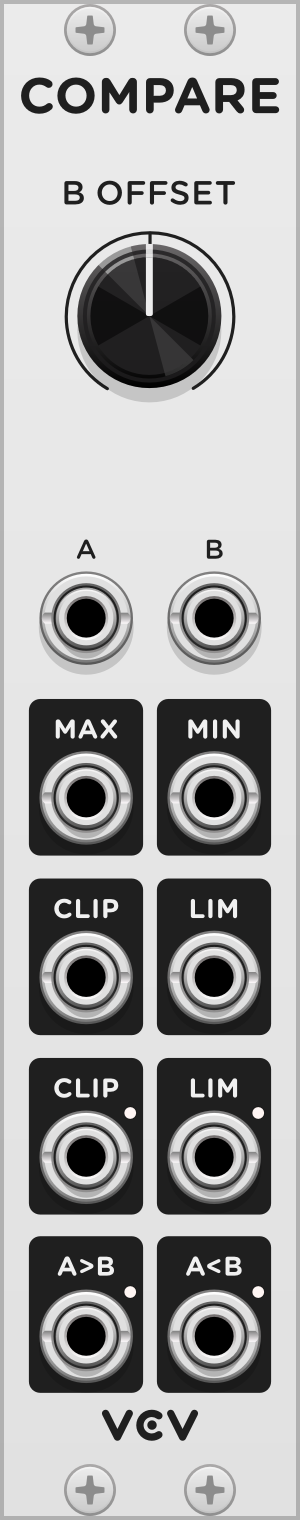
VCV Compare
This CV processor performs various comparisons between two CV signals A and B
The B OFFSET knob adds a fixed offset to the B voltage, or sets the voltage directly if B is unpatched.
MAX is the largest value of A and B. For example, if A is 3V and B is 6V, MAX is 6V.
MIN is the smallest value of A and B. For example, if A is 3V and B is 6V, MIN is 3V.
The CLIP CV output processes signal A by clipping it to the range -B to B. For example, if B is 5V, all values of A below -5V are limited to -5V, and all values above 5V are limited to 5V. Values of A between -5V and 5V are unchanged.
The LIM CV output outputs the portion of the A signal that is beyond the range -B to B. For example, if A is 8V and B is 5V, A is beyond 5V by 3V, so LIM is 3V. Values of A between -5V and 5V result in LIM of 0V, since A is not beyond this range.
Note: CLIP + LIM is always equal to A, so you can think of these two outputs as breaking the A signal into two parts.

The CLIP gate output (below the CLIP CV output) is HIGH when A is outside the range -B to B.
The LIM gate output (below the LIM CV output) is HIGH when A is inside the range -B to B.
A>B is a gate that is HIGH when the A voltage is greater than the B voltage.
A<B is a gate that is HIGH when the A voltage is less than the B voltage.

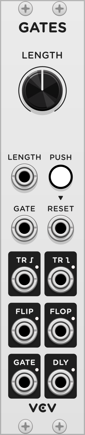
VCV Gates
Gates includes several functions for processing and converting gate and trigger signals.
The rising edge and falling edge outputs produce a 1 ms trigger when the gate input signal rises and falls, respectively.
The FLIP and FLOP gate outputs alternate in state when a trigger is received. FLIP is activated when the module is reset with a RESET trigger or button press.
The GATE output rises when a trigger is received and falls after the duration specified with the LENGTH knob. This can be used to convert a trigger into a gate of a specified duration. The gate can be deactivated immediately with a RESET trigger.
The DLY gate delay output records and delays the gate signal by LENGTH. The recorded signal can be cleared with a RESET trigger.

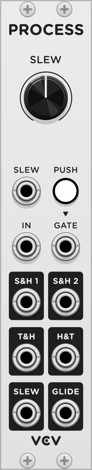
VCV Process
Process includes several functions for processing a CV signal over time.
The S&H 1 sample-and-hold output memorizes and holds the IN voltage whenever a GATE trigger is received. When another trigger is received, S&H 1 is reset to the new value, and its old value is set to S&H 2. These two outputs operate as a 2-step shift register.


The T&H track-and-hold output holds the IN voltage when GATE is high and passes the IN voltage when GATE is low.

The H&T hold-and-track output is similar to T&H but holds the IN voltage when GATE is low and passes the IN voltage when GATE is high.

A slew limiter prevents the rate of change of a signal from exceeding a certain rate. The SLEW output slew-limits the IN signal according to the SLEW rate parameter in units of ms/V (milliseconds per volt). When GATE is high, the SLEW output jumps to and follows the IN voltage.

The GLIDE output is similar to the SLEW output, but its gate logic is inversed. The IN signal is slew-limited only when the GATE is high. Another subtle difference is that slew-limiting is enabled 1 ms after the GATE rises, to prevent a slightly late IN signal change from being slew-limited.


VCV Mult
A “signal multiple” module copies one signal to several outputs, so a single audio/CV/gate source can be sent to multiple destinations. VCV Mult is an 8-output multiple.
In VCV Rack, any number of cables can be stacked on a single output port with Ctrl-drag (Cmd-drag on Mac), so a multiple module is often unnecessary when creating patches in Rack. However, VCV Mult is useful for a few purposes other than simply copying a signal:
- Easily accessing all cable plugs without needing to right-click on a stack of plugs.
- Transporting a signal to an area of the patch where many copies of the signal are needed. This prevents cluttering the screen with several long cables from the same output.
- Precisely replicating Eurorack patches where multiples are used.
- Adding 1 extra sample of latency to a signal chain. In VCV Rack, cables delay their signal by 1 sample, and certain timing-fragile patches may require delaying a signal by 2 or more samples.

VCV Rescale
VCV Rescale amplifies/attenuates, offsets, and optionally limits a CV or audio signal. This can be useful for adjusting the voltage range of a signal.
Gain is first applied to the IN signal by multiplying the voltage by a percentage. For example, a gain of 50% multiplies the signal by 0.5, halving it. A gain of 100% leaves the signal unchanged. Negative gain values invert the signal.
By default, you can apply between 1x (100%) and -1x (-100%) of gain. Right-click the panel to set the “Gain multiplier” to 1x, 10x, 100x, or 1000x for extra signal boost.

An offset voltage can be applied to the gain-processed signal. This adds a fixed voltage to the signal, between +10V and -10V.

Using gain and offset, you can rescale any voltage signal range to any other, such as the following common conversions.
- 0V—10V to -5V—5V: 100% gain, -5V offset
- -5V—5V to 0V—10V: 100% gain, +5V offset
- 0V—10V to -10V—10V: 2x gain, -10V offset
- -10V—10V to 0V—10V: 50% gain, +5V offset
Range limiting
The signal is limited by the MAX and MIN knobs, initially set to 10V and -10V. The OUT signal cannot exceed these bounds, after gain and offset is applied.

Right-click the panel and select “Reflect at maximum” and/or “Reflect at minimum” to reflect, rather than limit, the voltage to the MAX and MIN bounds. If both settings are enabled, the signal can reflect multiple times between MAX and MIN values.


VCV Random Values
VCV Random Values generates 7 fixed random voltage values, which can be re-randomized with the PUSH button or TRIG trigger input. Each output generates a different random value, so you can independently randomize multiple CV inputs in your patch.
Right-click the panel to change the “Random range” of the value generator. When new values are generated with PUSH or TRIG, values will fall inside this range.
All random values are saved/recalled in your patch, so modules modulated by these values will sound the same when the patch is reloaded, until VCV Random Values is re-randomized.

VCV Push
VCV Push allows you to manually generate a trigger pulse or gate signal by pressing a button.
The TRIG output generates a 1 ms trigger signal when the large button is pressed down. The GATE output generates a 10V gate signal while the large button is held.

Press the HOLD button or trigger the HOLD input to hold the gate state. When enabled, pressing the large button temporarily disables the gate state until released.

Send a gate to the PUSH input to override the push button state.
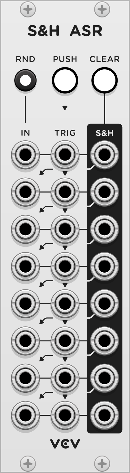
VCV Sample & Hold Analog Shift Register
VCV S&H ASR combines the concepts of a Sample & Hold module, which “freezes” an input voltage when triggered, and an Analog Shift Register, which shifts voltage values down an array of outputs when triggered.
When each row is triggered by its TRIG input, the current IN voltage is sampled and held at the S&H output until triggered again. Each TRIG input is normalized to the input above it, so a trigger sent to a row is sent to all TRIG inputs below it, until a patched TRIG input is reached. The PUSH button triggers row 1, which triggers all rows below it until a patched TRIG input is reached.
Each row’s IN input is normalized to the S&H output of the row above it. This allows the array of S&H outputs to act as an Analog Shift Register when the IN inputs are unpatched. For example, when PUSH is pressed, the current IN 1 signal is sampled to S&H 1, the old S&H 1 value is moved to S&H 2, the old S&H 2 value is moved to S&H 3, and so on.

Press CLEAR to set all S&H outputs to 0V.
Press RND to normalize IN 1 to a random signal. When enabled, triggering row 1 with an unpatched IN 1 input will sample a random voltage to S&H 1. Right-click the panel to change the “Random range” of the random generator.
All S&H output voltages are saved/recalled in your patch, so reloading your patch or restarting Rack restores all sampled voltages.

Did we miss anything in this manual? Let us know at VCV Support and so we can improve it!
VCV Free Changelog
2.6.5 (in development)
- VCO
- Make sine output pure (-103 dB THD) instead of quadratically-shaped with harmonics.
- Expand frequency range to about 3–21,000 Hz.
- Add DC blocker to all outputs.
- Improve performance.
- Fix glitching at high frequencies, extreme pulse widths, and fast sync signals.
- VCF
- Improve stability with TPT (Topology-Preserving Transform) solver.
- Decrease aliasing with ADAA.
- Increase maximum cutoff frequency to 22,000 Hz.
2.6.4 (2025-08-16)
- Random
- Fix Smooth output discontinuity.
2.6.3 (2025-05-03)
- VCO
- Fix occasional clicking in square wave output when modulating pulse width.
- Wavetable VCO/LFO
- Fix crash in v2.6.2 when loading/saving wavetables on Windows.
- Random
- Make External input polyphonic.
- Delay
- Clip wet signal at ±100 V.
2.6.2 (2025-04-15)
- Random
- Fix “Random spread” slider being reset to 100% after Randomizing module and reloading patch.
2.6.1 (2024-11-21)
- Wavetable VCO / LFO
- Allow loading AIFF wavetables.
- Fix crash when loading wavetable with less than 32 samples.
- Rescale
- Add min/max lights.
2.6.0 (2023-10-10)
- Add modules Rescale, Random Values, Push, and S&H ASR.
2.5.1 (2023-08-13)
- Add dark panels.
2.5.0 (2023-05-31)
- Fade
- Add -3 dB pan law to settings.
- Quantizer
- Add “Shift notes up/down” menu items.
- CV Mix
- When mixing mono and poly signals, apply mono signal to all poly channels.
- Improve performance with SIMD.
- VCA Mix
- Add settings for exponential channel and mix VCAs.
- Sequential Switch 1 to 4 & 4 to 1
- Add de-click setting to context menu. Disable de-click by default.
- When mixing mono and poly signals, apply mono signal to all poly channels.
- SEQ 3
- Generate step 1 pulse output when resetting from a different step.
- ADSR
- Redesign envelope display.
2.4.0 (2023-04-01)
- Add Mult.
- SEQ 3
- Reset step phase when reset trigger is received.
- Mutes
- Add bypass routes.
- VCA
- Fix graphical glitch when display segments have 0% height.
2.3.1 (2022-08-07)
- Logic
- Fix polyphonic outputs.
2.3.0 (2022-07-15)
- Add Logic.
- Add Compare.
- Add Gates.
- Add Process.
- Mid/Side
- Normalize decoder mid/side inputs to encoder mid/side outputs.
2.2.1 (2022-05-24)
- CV Mix
- Normalize all inputs to 10V instead of just the first input.
2.2.0 (2022-05-22)
- Add CV Mix.
- Add Fade.
2.1.0 (2022-01-23)
- VCA Mix
- When mixing polyphonic and monophonic signals, don’t copy monophonic signals to all polyphonic channels. Simply mix them to polyphonic channel 1.
- Scope
- Change TRIG param options from External/Internal to Disabled/Enabled. External trigger input now requires TRIG param to be enabled.
- Fix min/max points being read from different buffer phases, creating visual glitches in the waveform plot.
2.0.3 (2021-12-31)
- Wavetable VCO and LFO
- Make wavetable loading lock-free, fixing hiccups and increasing performance.
2.0.2 (2021-12-26)
- Wavetable VCO and LFO
- Fix probabilistic crash when loading wavetable files.
2.0.1 (2021-12-18)
- Random
- Fix rate frequency being 2 times higher than display value.
2.0.0 (2021-11-30)
- Mixer
- When polyphonic and monophonic inputs are combined, copy all mono signals to all mix output poly channels.
1.4.1 (2020-07-15)
- Improve VCF model accuracy and stability.
1.4.0 (2019-11-08)
- Add Pulses.
1.3.1 (2019-10-19)
- Include LEDSliderHandle.svg from Rack v1.1.5 so older versions correctly render panels.
1.3.0 (2019-10-19)
- Add Random and Noise modules.
- Make VCA-1 display polyphonic CV.
- Add VU meters to level sliders in Mixer.
1.2.1 (2019-08-10)
- Fix VCO hard sync bug, resulting in aliasing.
1.2.0 (2019-07-30)
- Add Quantizer.
- Add CV input to Octave.
1.1.1 (2019-07-24)
- Mid/Side: fix scaling of decoder.
1.1.0 (2019-07-22)
- Add Mid/Side.
1.0.1 (2019-06-27)
- Fix VCO-1/2 sync being triggered with a negative slope.
1.0.0 (2019-06-19)
- Migrate to v1 API.
- Add performance optimizations with SIMD.
- Change brand to “VCV”, so modules appear as “VCV VCO-1”, etc.
- Make most modules polyphonic.
- Change VCO-1/2 method from oversampling to MinBLEP.
0.5.1 (2017-12-19)
- Added Sequential Switch 1 & 2.
0.5.0 (2017-11-21)
- Added 8vert, 8-channel attenuverter.
- Added Unity, 2-channel mixer.
- Changed LED functions in ADSR.
0.4.0 (2017-10-13)
- Added Lissajous mode to Scope.
- Added two LFOs and VCO-2.
0.3.2 (2017-09-25)
- Fixed Drive CV input of VCF.
- Reverted SEQ3 to continuous gates.